
- 行业
- Industry
- 石油钻采 · 牙轮钻头
- Oil & gas drilling
- 零件
- Part
- 牙掌(bit leg)
- Bit leg
- 工况
- Operations
- 强断续车削 / 连续车削 / 槽加工
- Heavy interrupted turning / continuous turning / grooving
- 牌号
- Grades
- HPN6003 · HPN3002
- 单刃件数
- Pieces per edge
- 40–80 / 100–200 / 100–200
- 40–80 / 100–200 / 100–200
- 材料方案
- Edge material
- CBN ≥90%(断续)· 约 50%(连续)· 粒度 2–3 μm
- CBN ≥90% (interrupted) · approx. 50% (continuous) · 2–3 μm grain
一、背景与零件信息
牙掌是石油牙轮钻头的三大件之一,与牙轮、水眼共同组成钻头主体,承担轴颈支撑与密封配合。需要车削的部位包括轴颈外圆、端面、台阶、密封槽与挡圈槽;部分结构还需加工轴承位。
牙掌通常采用渗碳钢,经渗碳淬火后表层硬度显著提高,心部保持韧性。本文未获得该批零件的具体材料牌号与硬度值,零件牌号、硬度与余量以客户图纸与工艺文件为准;此处按“表层高硬度、余量不均、存在油孔与水眼孔造成的断续”这一典型工况描述。
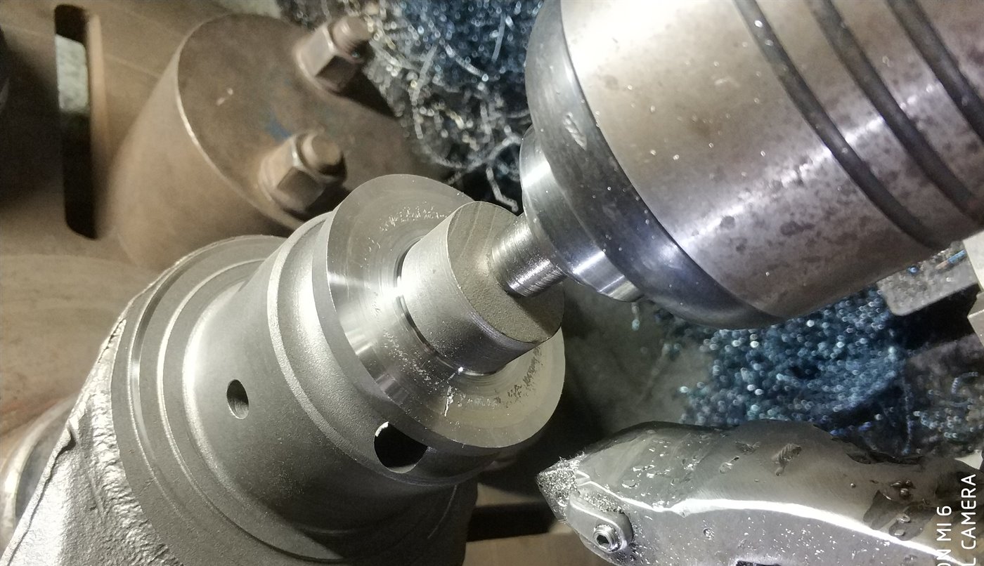
加工设备为数控车床,采用卡盘装夹,现场照片即车削工位。批量生产意味着刀具寿命直接决定换刀频次与单件节拍。
二、工况难点
- 强断续冲击:油孔、水眼孔与键槽使刃口每转承受多次冲击,崩刃与微崩是主要失效形式。
- 表面硬度高:切削力大、热量集中在刃口附近,后刀面磨损快。
- 硬度梯度:渗碳层与心部硬度差异导致切削力波动,同一刃口在不同切深处磨损不均。
- 余量不均:毛坯余量分布不一致,切入瞬间的冲击载荷难以完全规避。
- 槽加工排屑:槽宽窄、排屑空间小,切屑易划伤已加工表面并引起振动。
- 质量要求:轴颈尺寸公差、同轴度与表面粗糙度需稳定,刀具磨损必须可控。
三、刀具方案
按工序分工,采用两类 CBN 牌号与三种刃型结构,现场单刃件数如下表。数据来自客户现场使用记录,实际寿命随余量、装夹与参数变化。
| 工序 | 牌号 | 规格型号 | CBN 含量 / 粒度 | 单刃件数 |
|---|---|---|---|---|
| 强断续车削 | HPN6003 | CNGA120408-2N CNGA120412-2N | ≥90% / 2–3 μm | 40–80 件 |
| 连续车削 | HPN3002 | CNGA120404-2N CNGA120408-2N CCGW09T304-2N | 约 50% / 2–3 μm | 100–200 件 |
| 槽加工 | HPN6003 | MGMN600-N | ≥90% / 2–3 μm | 100–200 件 |
选型逻辑:强断续工序优先抗冲击,选用高 CBN 含量牌号并配合韧性刃口处理;连续工序以耐磨与表面质量为主,选用中等含量牌号与较锋利的刃口;槽加工沿用高含量牌号,依靠窄刃型与排屑空间控制失效。
四、切削参数
现场连续与断续两类工序的参数区间如下。参数由客户工艺设定,实际使用时结合试切结果与机床条件调整。
| 工序 | 线速度 Vc | 吃刀深度 ap | 进给量 f |
|---|---|---|---|
| 连续车削 | 80–150 m/min | 0.1–0.3 mm | 0.05–0.15 mm/r |
| 强断续车削 | 60–100 m/min | 0.1–0.5 mm | 0.05–0.2 mm/r |
槽加工(MGMN600-N)的具体参数未随本案例提供,建议按槽宽、排屑与振动情况单独试切确定。
- 断续工序吃刀深度上限 0.5 mm,避免持续超过刃口倒棱宽度。
- 连续工序线速度上限 150 m/min,以表面粗糙度与后刀面磨损作为调整依据。
- 每轮试切记录 Vc、f、ap、冷却方式与机床功率,便于复现。
注:进给量按车削常用单位 mm/r 标注;如现场采用其他口径,以工艺文件为准。
五、寿命与失效分析
现场单刃寿命为:强断续 40–80 件,连续 100–200 件,槽加工 100–200 件。三类工序的失效形式不同:强断续以崩刃和微崩为主,连续工序以后刀面磨损为主,槽加工则以刃口磨损与排屑划伤为主。
影响寿命的主要因素包括余量均匀性、装夹刚性、冷却方式与参数设定。判定换刃的参考标准为:崩刃面积超过刃口有效长度的一定比例、后刀面磨损带超限,或表面粗糙度与尺寸出现超差趋势。
六、应用效果与对比
在该客户现场,三类工序均达到上表所列单刃件数,换刀间隔相对稳定,轴颈尺寸与表面质量满足要求。由于未取得原用刀具的对照记录,本案例不做倍数比较;如需量化提升,应按同一零件、同一参数做对照试切。
方案的直接价值在于“按工序分工”:强断续与连续工况不再共用一种刃口,减少因通用牌号在不匹配工况下提前失效带来的换刀损失。
七、结论与建议
- 强断续车削优先 HPN6003(CNGA120408-2N / CNGA120412-2N),以抗冲击为先。
- 连续车削优先 HPN3002(CNGA120404-2N / CNGA120408-2N / CCGW09T304-2N),以耐磨与表面质量为先。
- 槽加工采用 MGMN600-N(HPN6003),重点控制排屑与振动。
- 建议先小批量试切,记录每刃件数与失效形式,再固化参数并批量下单。
如需针对具体牙掌零件的选型建议,请提供零件图、材料牌号与硬度、机床型号、余量分布与目标节拍,我们会匹配刃型与牌号并给出试切方案。
1. Background and part information
The bit leg is one of the three main components of a roller cone bit, together with the cone and the nozzle. It carries the journal support and the sealing interface. Turning operations cover the journal OD, faces, steps, seal grooves and retaining grooves; some structures also require bearing seats.
Bit legs are usually made of carburising steel, case-hardened to a high surface hardness while the core remains tough. The specific grade and hardness of this batch were not provided; grade, hardness and stock allowance follow the customer's drawing and process documents. The description here follows the typical condition of high surface hardness, uneven stock and interruption caused by oil holes and nozzle holes.
Machining uses CNC lathes with chuck clamping; the photo shows the turning station. In batch production, tool life directly determines tool-change frequency and cycle time.
2. Process difficulties
- Heavy interruption: oil holes, nozzle holes and keyways subject the edge to multiple impacts per revolution; chipping and micro-chipping are the main failure modes.
- High surface hardness: high cutting forces and concentrated heat accelerate flank wear.
- Hardness gradient: the difference between case and core causes force fluctuation and uneven wear along the depth of cut.
- Uneven stock: inconsistent allowance makes the entry impact hard to avoid entirely.
- Groove chip evacuation: narrow grooves leave little room for chips, which can scratch the machined surface and cause vibration.
- Quality requirements: journal tolerance, coaxiality and surface roughness must remain stable, so wear has to be controlled.
3. Tooling combination
Two CBN grades and three edge structures are assigned by operation. Pieces per edge below come from the customer's site records; actual life varies with allowance, clamping and parameters.
| Operation | Grade | Models | CBN / grain | Pieces per edge |
|---|---|---|---|---|
| Heavy interrupted turning | HPN6003 | CNGA120408-2N CNGA120412-2N | ≥90% / 2–3 μm | 40–80 |
| Continuous turning | HPN3002 | CNGA120404-2N CNGA120408-2N CCGW09T304-2N | approx. 50% / 2–3 μm | 100–200 |
| Grooving | HPN6003 | MGMN600-N | ≥90% / 2–3 μm | 100–200 |
Selection logic: interrupted operations prioritise impact resistance with a high-CBN grade and a tough edge preparation; continuous operations prioritise wear resistance and surface quality with a medium-content grade and a sharper edge; grooving keeps the high-CBN grade and relies on a narrow profile and chip clearance to control failure.
4. Cutting parameters
Parameter ranges for the continuous and interrupted operations on site are shown below. They are set by the customer's process and should be adjusted by trial cutting and machine conditions.
| Operation | Cutting speed Vc | Depth of cut ap | Feed f |
|---|---|---|---|
| Continuous turning | 80–150 m/min | 0.1–0.3 mm | 0.05–0.15 mm/rev |
| Heavy interrupted turning | 60–100 m/min | 0.1–0.5 mm | 0.05–0.2 mm/rev |
Specific parameters for grooving (MGMN600-N) were not supplied with this case; set them by trial cutting according to groove width, chip evacuation and vibration.
- Interrupted operations: keep depth of cut within 0.5 mm and avoid continuously exceeding the chamfer width.
- Continuous operations: cap cutting speed at 150 m/min and adjust by surface roughness and flank wear.
- Record Vc, f, ap, cooling method and machine power in each trial for repeatability.
Note: feed is given in mm/rev, the common turning convention; if another convention applies on site, follow the process documents.
5. Life and failure analysis
Site results: 40–80 pieces per edge in interrupted turning, 100–200 in continuous turning and 100–200 in grooving. Failure modes differ: chipping and micro-chipping dominate interrupted work, flank wear dominates continuous work, and edge wear with chip scratching dominates grooving.
Main influencing factors are stock uniformity, clamping rigidity, cooling and parameters. Change-over references include chipping area exceeding a set share of the effective edge length, flank wear beyond limit, or a trend of roughness and dimensional deviation.
6. Results and comparison
At this customer site all three operations reached the piece counts above, with relatively stable tool-change intervals and acceptable journal dimensions and surface quality. No records from the previous tooling were available, so this case makes no multiple-based comparison; a quantified improvement requires a controlled trial on the same part and parameters.
The direct value is task-based assignment: interrupted and continuous operations no longer share one edge, reducing losses from a general-purpose grade failing early in a mismatched condition.
7. Conclusions and recommendations
- For heavy interrupted turning, use HPN6003 (CNGA120408-2N / CNGA120412-2N), impact resistance first.
- For continuous turning, use HPN3002 (CNGA120404-2N / CNGA120408-2N / CCGW09T304-2N), wear resistance and surface quality first.
- For grooving, use MGMN600-N (HPN6003), focusing on chip evacuation and vibration.
- Run a small trial batch, record pieces per edge and failure modes, then fix parameters and order in batches.
For selection advice on a specific bit leg, provide the part drawing, material grade and hardness, machine model, stock distribution and target cycle time; we will match edge geometry and grade and propose a trial plan.